- Seite 1 und 2:
Deutsch English Polskie Français
- Seite 3 und 4:
INHALT 1.0 EINLEITUNG .............
- Seite 5 und 6:
1.2 Beschreibung 7 4 3 5 8 1 10 2 6
- Seite 7 und 8:
Abstand Felge zu Maschine Felgenbre
- Seite 9 und 10:
1.3.3. Auswahl der Auswuchtart DYN
- Seite 11 und 12:
) Rad-Daten und Eingabe zur Berechn
- Seite 13 und 14:
Nach dem Auswuchtvorgang kann das H
- Seite 15 und 16:
Zum Starten des Optimierungs-Vorgan
- Seite 17 und 18:
1.5. Maßzeichnung 1900 mm 1090 mm
- Seite 19 und 20:
2.2 Auspacken der Maschine Entferne
- Seite 21 und 22:
Konus 45-71mm Konus 69-91mm Konus 8
- Seite 23 und 24:
2.5 Befestigung Hierbei sind die al
- Seite 25 und 26:
2.9.2 Befestigung mittels Sicherhei
- Seite 27 und 28:
Entfernen Sie nun die Befestigungss
- Seite 29 und 30:
Einstellung Gewichtspositionierung:
- Seite 31 und 32:
Durch Drücken der START-Taste oder
- Seite 33 und 34:
2.9.11 Kalibrierung der Gewichtsauf
- Seite 35 und 36: Auf dem Display erscheint die Anzei
- Seite 37 und 38: 3.2 Grundsätzliche Hinweise Mit de
- Seite 39 und 40: Druckluftanlage Mindestanforderung:
- Seite 41 und 42: 4.5 Fehleranzeige und Abhilfe Der W
- Seite 43 und 44: 4.6 Wartungs- und Serviceanleitunge
- Seite 45 und 46: 5.0 EG-/EU-KONFORMITÄTSERKLÄRUNG
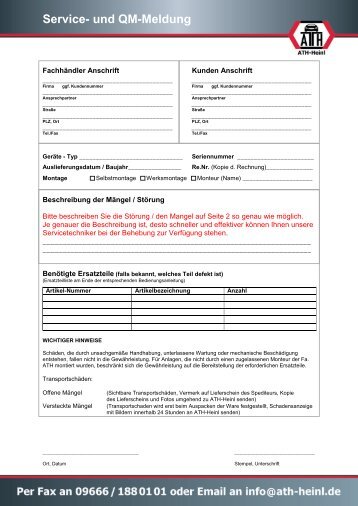
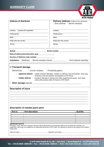
- Seite 47 und 48: 7.0 GARANTIEKARTE Fachhändler Ansc
- Seite 49 und 50: 8.0 PRÜFBUCH Dieses Prüfbuch (ink
- Seite 51 und 52: 8.2 Prüfplan Prüfung 1 2 3 4 5 6
- Seite 53 und 54: Sichtprüfung (Befugte Sachkundige
- Seite 55 und 56: Sichtprüfung (Befugte Sachkundige
- Seite 57 und 58: Sichtprüfung (Befugte Sachkundige
- Seite 59 und 60: ® Urheberrecht ATH-Heinl GmbH & CO
- Seite 61 und 62: www.ath-heinl.de ATH-Heinl GmbH & C
- Seite 63 und 64: Contents 1.0 INTRODUCTION .........
- Seite 65 und 66: 1.2 Description 7 4 3 5 8 1 10 2 6
- Seite 67 und 68: Distance between rim and machine Ri
- Seite 69 und 70: 1.3.3 Selecting the balancing type
- Seite 71 und 72: ) Wheel data and entries for calcul
- Seite 73 und 74: After the balancing process, the HI
- Seite 75 und 76: Press the “STOP” + “MODEL”
- Seite 77 und 78: 1.5 Scale Drawing 1900 mm 1090 mm 1
- Seite 79 und 80: 2.2 Unpacking the machine Remove th
- Seite 81 und 82: Cone 45-71 mm Cone 69-91 mm Cone 89
- Seite 83 und 84: 2.5 Fixing General and local regula
- Seite 85: 2.9.2. Securing using the safety an
- Seite 89 und 90: Adjustment of weight attachment: In
- Seite 91 und 92: The second balancing process for th
- Seite 93 und 94: 2.9.11. Calibrating the weight sens
- Seite 95 und 96: The display shows [CAL.] - [15.0] T
- Seite 97 und 98: 3.2 Basic Information Independent o
- Seite 99 und 100: Compressed air system Minimum requi
- Seite 101 und 102: 4.5 Troubleshooting / Error Display
- Seite 103 und 104: 4.6 Maintenance and Service Instruc
- Seite 105 und 106: 5.0 EG-/EU-KONFORMITÄTSERKLÄRUNG
- Seite 107 und 108: 7.0 WARRANTY CARD Dealer address: C
- Seite 109 und 110: 8.0 INSPECTION LOG This inspection
- Seite 111 und 112: 8.2 Inspection Plan Inspection 1 2
- Seite 113 und 114: Visual inspection (authorised exper
- Seite 115 und 116: Visual inspection (authorised exper
- Seite 117 und 118: Visual inspection (authorised exper
- Seite 119 und 120: ® Copyright ATH-Heinl GmbH & Co. K
- Seite 121 und 122: www.ath-heinl.de ATH-Heinl GmbH & C
- Seite 123 und 124: Sommaire 1.0 INTRODUCTION .........
- Seite 125 und 126: 1.2 Description 7 4 3 5 8 1 10 2 6
- Seite 127 und 128: Distance entre jante et équilibreu
- Seite 129 und 130: 1.3.3 Sélection du type de balourd
- Seite 131 und 132: ) Données de roue et saisie pour c
- Seite 133 und 134: Une fois la procédure d'équilibra
- Seite 135 und 136: Appuyez sur le bouton START + MODAL
- Seite 137 und 138:
1.5 Croquis coté 1900 mm 1090 mm 1
- Seite 139 und 140:
2.2 Déballage de la machine Retire
- Seite 141 und 142:
Cône 45 à 71 mm Cône 69 à 91 mm
- Seite 143 und 144:
2.5 Fixation Il convient ici de res
- Seite 145 und 146:
2.9.2. Fixation par chevilles de s
- Seite 147 und 148:
2.9.4. Montage du carter de protect
- Seite 149 und 150:
2.9.7. Paramètres système Les par
- Seite 151 und 152:
2.9.9. Calibrage des supports de ma
- Seite 153 und 154:
L'indication [CAL.] - [End] appara
- Seite 155 und 156:
Placez ensuite le doigt de mesure a
- Seite 157 und 158:
3.2 Remarques générales Seules de
- Seite 159 und 160:
Installation d'air comprimé Exigen
- Seite 161 und 162:
4.5 Dépannage / Affichage des déf
- Seite 163 und 164:
4.6 Instructions de maintenance et
- Seite 165 und 166:
5.0 EG-/EU-KONFORMITÄTSERKLÄRUNG
- Seite 167 und 168:
7.0 CARTE DE GARANTIE Adresse du re
- Seite 169 und 170:
8.0 REGISTRE DE CONTRÔLE Ce regist
- Seite 171 und 172:
8.2 Plan de contrôle Contrôle 1 2
- Seite 173 und 174:
Contrôle visuel (personne qualifi
- Seite 175 und 176:
Contrôle visuel (personne qualifi
- Seite 177 und 178:
Contrôle visuel (personne qualifi
- Seite 179 und 180:
® Droit d'auteur ATH-Heinl GmbH &
- Seite 181 und 182:
www.ath-heinl.de ATH-Heinl GmbH & C
- Seite 183 und 184:
Obsah 1.0 ÚVOD ...................
- Seite 185 und 186:
1.2 Popis 7 4 3 5 8 1 10 2 6 9 1. h
- Seite 187 und 188:
vzdálenost ráfku od stroje šíř
- Seite 189 und 190:
1.3.3 Volba typu nevyváženosti DY
- Seite 191 und 192:
) Údaje o kole a zadávané údaje
- Seite 193 und 194:
Poté se zobrazí ukazatel SPO - 12
- Seite 195 und 196:
Pro spuštění optimalizace stiskn
- Seite 197 und 198:
1.5 Rozměrový výkres 1900 mm 164
- Seite 199 und 200:
2.2 Vybalení stroje Sejměte horn
- Seite 201 und 202:
Kužel 45-71 mm Kužel 69-91 mm Ku
- Seite 203 und 204:
2.5 Upevnění Zde je potřebné se
- Seite 205 und 206:
2.9.2. Upevnění pomocí bezpečno
- Seite 207 und 208:
2.9.4. Montáž obloukového chrán
- Seite 209 und 210:
2.9.7. Systémová nastavení Pomoc
- Seite 211 und 212:
Upněte již vyvážené kolo (nap
- Seite 213 und 214:
Na displeji se zobrazí ukazatel [C
- Seite 215 und 216:
Stiskněte tlačítko ALU Na disple
- Seite 217 und 218:
3.2 Zásadní upozornění Stroj sm
- Seite 219 und 220:
Minimální požadavky na montážn
- Seite 221 und 222:
4.5 Hledání závad / Indikace zá
- Seite 223 und 224:
4.6 Návody k údržbě a servisní
- Seite 225 und 226:
5.0 EG-/EU-KONFORMITÄTSERKLÄRUNG
- Seite 227 und 228:
7.0 ZÁRUČNÍ KARTA Adresa odborn
- Seite 229 und 230:
8.0 KONTROLNÍ DENÍK Tento kontrol
- Seite 231 und 232:
8.2 Harmonogram kontrol Kontrol 1 2
- Seite 233 und 234:
Vizuální kontrola (povolanou odbo
- Seite 235 und 236:
Vizuální kontrola (povolanou odbo
- Seite 237 und 238:
Vizuální kontrola (povolanou odbo
- Seite 239 und 240:
® Copyright ATH-Heinl GmbH & CO.KG
- Seite 241 und 242:
www.ath-heinl.de ATH-Heinl GmbH & C
- Seite 243 und 244:
Índice 1.0 INTRODUCCIÓN .........
- Seite 245 und 246:
1.2 Descripción 7 4 3 5 8 1 10 2 6
- Seite 247 und 248:
Distancia llanta a máquina Anchura
- Seite 249 und 250:
1.3.3 Selección del tipo de equili
- Seite 251 und 252:
) Datos de rueda y entrada para el
- Seite 253 und 254:
Después, la pantalla mostrará SPO
- Seite 255 und 256:
Para iniciar el proceso de optimiza
- Seite 257 und 258:
1.5 Dibujo acotado 1900 mm 1090 mm
- Seite 259 und 260:
2.2 Desembalaje de la máquina Reti
- Seite 261 und 262:
Cono 45-71 mm Cono 69-91 mm Cono 89
- Seite 263 und 264:
2.5 Fijación Deberán tenerse en c
- Seite 265 und 266:
2.9.2. Fijación con anclaje de seg
- Seite 267 und 268:
2.9.4. Instalación de la cubierta
- Seite 269 und 270:
2.9.7. Ajuste del sistema Es posibl
- Seite 271 und 272:
Sujete una rueda ya equilibrada (po
- Seite 273 und 274:
2.9.11. Calibración del soporte de
- Seite 275 und 276:
La pantalla mostrará [CAL.] - [15.
- Seite 277 und 278:
3.2 Indicaciones básicas El manejo
- Seite 279 und 280:
Requisito mínimo para máquina de
- Seite 281 und 282:
4.5 Búsqueda de fallos/Visualizaci
- Seite 283 und 284:
4.6 Guías de mantenimiento y servi
- Seite 285 und 286:
5.0 EG-/EU-KONFORMITÄTSERKLÄRUNG
- Seite 287 und 288:
7.0 TARJETA DE GARANTÍA Dirección
- Seite 289 und 290:
8.0 LIBRO DE INSPECCIÓN Este libro
- Seite 291 und 292:
8.2 Plan de inspección Inspección
- Seite 293 und 294:
Inspección visual (especialista au
- Seite 295 und 296:
Inspección visual (especialista au
- Seite 297 und 298:
Inspección visual (especialista au
- Seite 299 und 300:
® Copyright ATH-Heinl GmbH & CO.KG
- Seite 301 und 302:
www.ath-heinl.de ATH-Heinl GmbH & C
- Seite 303 und 304:
Inhoud 1.0 INLEIDING ..............
- Seite 305 und 306:
1.2 Omschrijving 7 4 3 5 8 1 10 2 6
- Seite 307 und 308:
Afstand velg tot machine Breedte ve
- Seite 309 und 310:
1.3.3 Selectie van de balanceermeth
- Seite 311 und 312:
) Wielgegevens en invoer voor berek
- Seite 313 und 314:
Daarna wordt in de weergave SPO - 1
- Seite 315 und 316:
Om de optimalisatieprocedure te sta
- Seite 317 und 318:
1.5 Maatschets 1900 mm 1090 mm 1640
- Seite 319 und 320:
2.2 De machine uitpakken Verwijder
- Seite 321 und 322:
Conus 45-71mm Conus 69-91mm Conus 8
- Seite 323 und 324:
2.5 Bevestiging Hierbij moeten de a
- Seite 325 und 326:
2.9.2. Bevestiging met behulp van e
- Seite 327 und 328:
2.9.4. Montage van de wielafdekkap
- Seite 329 und 330:
2.9.7. Systeeminstellingen Met behu
- Seite 331 und 332:
Een reeds uitgebalanceerd wiel (bij
- Seite 333 und 334:
2.9.11. Kalibratie van de gewichtso
- Seite 335 und 336:
Op het display verschijnt de weerga
- Seite 337 und 338:
3.2 Fundamentele aanwijzingen De ma
- Seite 339 und 340:
Minimale eisen voor vrachtwagenband
- Seite 341 und 342:
4.5 Storingen opsporen/storingsmeld
- Seite 343 und 344:
4.6 Onderhouds- en servicehandleidi
- Seite 345 und 346:
5.0 EG-/EU-KONFORMITÄTSERKLÄRUNG
- Seite 347 und 348:
7.0 GARANTIEKAART Dealernaam: Bedri
- Seite 349 und 350:
8.0 TESTBOEK Dit testboek (inclusie
- Seite 351 und 352:
8.2 Inspectieschema Inspectie 1 2 3
- Seite 353 und 354:
Visuele inspectie (door geautorisee
- Seite 355 und 356:
Visuele inspectie (door geautorisee
- Seite 357 und 358:
Visuele inspectie (door geautorisee
- Seite 359 und 360:
® copyright ATH-Heinl GmbH & Co. K
- Seite 361 und 362:
www.ath-heinl.de ATH-Heinl GmbH & C
- Seite 363 und 364:
Spis treści 1.0 WPROWADZENIE .....
- Seite 365 und 366:
1.2 Opis 7 4 3 5 8 1 10 2 6 9 1. Wy
- Seite 367 und 368:
Odstęp felgi od maszyny Szerokoś
- Seite 369 und 370:
1.3.3 Wybór rodzaju wyważenia DYN
- Seite 371 und 372:
) Dane koła i wprowadzenie w celu
- Seite 373 und 374:
Następnie na wskaźniku wyświetli
- Seite 375 und 376:
Aby rozpocząć proces optymalizacj
- Seite 377 und 378:
1.5 Zwymiarowany rysunek 1900 mm 10
- Seite 379 und 380:
2.2 Rozpakowanie maszyny Zdjąć g
- Seite 381 und 382:
Stożek 45-71 mm Stożek 69-91 mm S
- Seite 383 und 384:
2.5 Mocowanie W tym przypadku nale
- Seite 385 und 386:
2.9.2. Zamocowanie za pomocą kotwy
- Seite 387 und 388:
2.9.4. Montaż osłony koła Wypako
- Seite 389 und 390:
2.9.7. Ustawienia systemowe Za pomo
- Seite 391 und 392:
Aby wejść do systemu kalibracji n
- Seite 393 und 394:
2.9.11. Kalibracja uchwytu ciężar
- Seite 395 und 396:
Na ekranie pojawia się wskaźnik [
- Seite 397 und 398:
3.2 Podstawowe informacje Maszynę
- Seite 399 und 400:
Minimalne wymaganie dotyczące masz
- Seite 401 und 402:
4.5 Wyszukiwanie błędów / Sygnal
- Seite 403 und 404:
4.6 Instrukcje dotyczące konserwac
- Seite 405 und 406:
5.0 EG-/EU-KONFORMITÄTSERKLÄRUNG
- Seite 407 und 408:
7.0 KARTA GWARANCYJNA Adres dealera
- Seite 409 und 410:
8.0 DZIENNIK BADAŃ Niniejszy dzien
- Seite 411 und 412:
8.2 Harmonogram kontroli Kontroli 1
- Seite 413 und 414:
Kontrola wzrokowa (upoważniona oso
- Seite 415 und 416:
Kontrola wzrokowa (upoważniona oso
- Seite 417 und 418:
Kontrola wzrokowa (upoważniona oso
- Seite 419 und 420:
® Prawa autorskie ATH-Heinl GmbH &
- Seite 421 und 422:
www.ath-heinl.de ATH-Heinl GmbH & C
- Seite 423 und 424:
Obsah 1.0 ÚVOD ...................
- Seite 425 und 426:
1.2 Opis 7 4 3 5 8 1 10 2 6 9 1. Hl
- Seite 427 und 428:
Vzdialenosť disku od stroja Šírk
- Seite 429 und 430:
1.3.3 Výber metódy vyvažovania D
- Seite 431 und 432:
) Údaje a zadávanie dát o kolese
- Seite 433 und 434:
Potom sa zobrazí indikátor SPO -
- Seite 435 und 436:
Na spustenie procesu optimalizácie
- Seite 437 und 438:
1.5 Rozmerový výkres 1900 mm 1090
- Seite 439 und 440:
2.2 Vybaľovanie stroja Snímte hor
- Seite 441 und 442:
Kužeľ 45 - 71 mm Kužeľ 69 - 91
- Seite 443 und 444:
2.5 Upevnenie Tu je potrebné riadi
- Seite 445 und 446:
2.9.2. Upevnenie pomocou istiacich
- Seite 447 und 448:
2.9.4. Montáž ochranného oblúko
- Seite 449 und 450:
2.9.7. Systémové nastavenia Pomoc
- Seite 451 und 452:
Už vyvážené koleso (napr. 22,5
- Seite 453 und 454:
2.9.11. Kalibrácia snímača záva
- Seite 455 und 456:
Na displeji sa zobrazí hlásenie [
- Seite 457 und 458:
3.2 Zásadné upozornenia Stroj sm
- Seite 459 und 460:
Zariadenie stlačeného vzduchu Min
- Seite 461 und 462:
4.5 Hľadanie chýb/indikácia chyb
- Seite 463 und 464:
4.6 Návody na údržbu a servisné
- Seite 465 und 466:
5.0 EG-/EU-KONFORMITÄTSERKLÄRUNG
- Seite 467 und 468:
7.0 ZÁRUČNÁ KARTA Adresa odborn
- Seite 469 und 470:
8.0 KONTROLNÝ DENNÍK Tento kontro
- Seite 471 und 472:
8.2 Harmonogram kontrol Kontrol 1 2
- Seite 473 und 474:
Zraková kontrola (povolanou odborn
- Seite 475 und 476:
Zraková kontrola (povolanou odborn
- Seite 477 und 478:
Zraková kontrola (povolanou odborn
- Seite 479 und 480:
® Copyright ATH-Heinl GmbH & CO.KG
- Seite 481:
www.ath-heinl.de ATH-Heinl GmbH & C


LinkedIn
Facebook
Instagram
Youtube
Email
Twitter
Pinterest