- Seite 2 und 3: Bedienungsanleitung ATH-Comfort Lif
- Seite 4 und 5: 1.0 EINLEITUNG 1.1 Allgemeine Infor
- Seite 6 und 7: Hauptbestandteile 1. Hubsäulen Der
- Seite 8 und 9: 1.3 Bedienung Hauptsäule 1. Taster
- Seite 10 und 11: Das Produkt ist zum Heben von Fahrz
- Seite 12 und 13: 1.4 Technische Daten Tragfähigkeit
- Seite 14 und 15: 1.5 Maßzeichnung 2.50a 2.50s Die a
- Seite 16 und 17: 2.3 Lieferumfang 1 Grundpaket mit:
- Seite 18 und 19: 2.4 Standort Die Maschine sollte vo
- Seite 20 und 21: 2.5 Befestigung Hierbei sind die al
- Seite 22 und 23: INSTALLATION Fundamentplan ATH Comf
- Seite 24 und 25: Max. Gefälle Härtezeit vom Beton:
- Seite 26 und 27: 2. Befestigung mittels Sicherheitsa
- Seite 28 und 29: Unterlegscheiben nicht montiert !!!
- Seite 30 und 31: 7. Hydraulikschlauch anbringen a. H
- Seite 32 und 33: 3.0 BETRIEB 3.1 Betriebsanweisung F
- Seite 34 und 35: 4.0 WARTUNG Um einen sicheren Betri
- Seite 36 und 37: 4.3 Hinweise Die Maschine ist, unab
- Seite 38 und 39: Probleme beim Senken Sicherheitsras
- Seite 40 und 41: 4.7 Entsorgung • Entfernen Sie di
- Seite 42 und 43: 6.0 ANHANG 6.1 Pneumatik-Schaltplan
- Seite 44 und 45: Q1 Hauptschalter SV Senkventil KM1
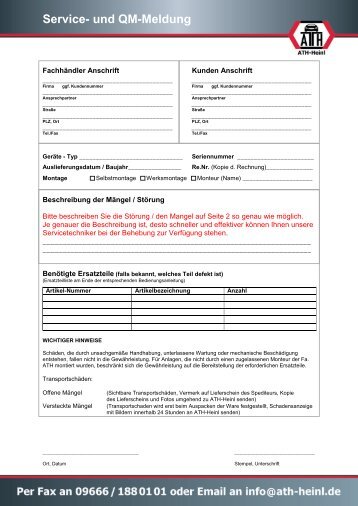
- Seite 46 und 47: 7.0 GARANTIEKARTE Fachhändler Ansc
- Seite 48 und 49: 8.0 PRÜFBUCH Dieses Prüfbuch (ink
- Seite 50 und 51: 8.2 Prüfplan Typenschild Kurzbedie
- Seite 52 und 53:
Sichtprüfung (Befugte Sachkundige
- Seite 54 und 55:
Sichtprüfung (Befugte Sachkundige
- Seite 56 und 57:
® Urheberrecht ATH-Heinl GmbH & CO
- Seite 58 und 59:
Operating Instructions ATH-Comfort
- Seite 60 und 61:
1.0 INTRODUCTION 1.1 General Inform
- Seite 62 und 63:
Main components 1. Pillars The insi
- Seite 64 und 65:
1.3 Operation Main column 1. Push b
- Seite 66 und 67:
This product is designed for liftin
- Seite 68 und 69:
1.4 Technical Data Capacity ATH-Com
- Seite 70 und 71:
1.5 Scale Drawing 2.50a 2.50s The g
- Seite 72 und 73:
2.3 Delivery Contents 1 Basis Packa
- Seite 74 und 75:
2.4 Location The machine should be
- Seite 76 und 77:
2.5 Fixing General and local regula
- Seite 78 und 79:
INSTALLATION Floor foundation ATH C
- Seite 80 und 81:
Max. inclination Concrete drying ti
- Seite 82 und 83:
2. Anchoring with the safety dowels
- Seite 84 und 85:
Waschers not installed Obstacle in
- Seite 86 und 87:
7. Installing of the hydraulic hose
- Seite 88 und 89:
3.0 OPERATION 3.1 Operating Instruc
- Seite 90 und 91:
4.0 MAINTENANCE The user must maint
- Seite 92 und 93:
4.3 Notes Regardless of the level o
- Seite 94 und 95:
Lowering Problems Check cable conne
- Seite 96 und 97:
4.7 Disposal • Remove the air and
- Seite 98 und 99:
6.0 APPENDIX 6.1 Pneumatic circuit
- Seite 100 und 101:
Q1 Main Switch SV Lowerin valve KM1
- Seite 102 und 103:
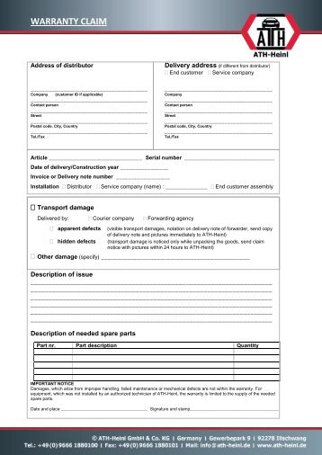
7.0 WARRANTY CARD Dealer address: C
- Seite 104 und 105:
8.0 INSPECTION LOG This inspection
- Seite 106 und 107:
8.2 Inspection Plan Nameplate Quick
- Seite 108 und 109:
Visual inspection (authorised exper
- Seite 110 und 111:
Visual inspection (authorised exper
- Seite 112 und 113:
® Copyright ATH-Heinl GmbH & Co. K
- Seite 114 und 115:
Manuel d‘Utilisation ATH-Comfort
- Seite 116 und 117:
1.0 INTRODUCTION 1.1 Informations g
- Seite 118 und 119:
Composants principaux 1. Colonnes d
- Seite 120 und 121:
1.3 Utilisation Colonne principale
- Seite 122 und 123:
1. Préparation a. Lisez attentivem
- Seite 124 und 125:
1.4 Caractéristiques techniques Ca
- Seite 126 und 127:
1.5 Croquis coté 2.50a 2.50s Ne pa
- Seite 128 und 129:
2.3 Livraison 1 Paquet de base avec
- Seite 130 und 131:
2.4 Lieu La machine doit être tenu
- Seite 132 und 133:
2.5 Fixation Il convient ici de res
- Seite 134 und 135:
INSTALLATION Plan de fondation ATH
- Seite 136 und 137:
Pente max. Temps de durcissement du
- Seite 138 und 139:
2. Fixation par chevilles de sécur
- Seite 140 und 141:
Rondelles non montées ! ! ! Obstac
- Seite 142 und 143:
7. Mettre en place le tuyau hydraul
- Seite 144 und 145:
3.0 EXPLOITATION 3.1 Manuel d'utili
- Seite 146 und 147:
4.0 MAINTENANCE Afin de garantir le
- Seite 148 und 149:
4.3 Remarques Quel que soit l'état
- Seite 150 und 151:
Problèmes lors de l'abaissement Le
- Seite 152 und 153:
4.7 Élimination • Coupez l'alime
- Seite 154 und 155:
6.0 ANNEXE 6.1 Schéma pneumatique
- Seite 156 und 157:
Q1 Interrupteur principal SV Soupap
- Seite 158 und 159:
7.0 CARTE DE GARANTIE Adresse du re
- Seite 160 und 161:
8.0 REGISTRE DE CONTRÔLE Ce regist
- Seite 162 und 163:
8.2 Plan de contrôle Plaque signal
- Seite 164 und 165:
Contrôle visuel (personne qualifi
- Seite 166 und 167:
Contrôle visuel (personne qualifi
- Seite 168 und 169:
® Droit d'auteur ATH-Heinl GmbH &
- Seite 170 und 171:
Návod k Obsluze ATH-Comfort Lift C
- Seite 172 und 173:
1.0 ÚVOD 1.1 Obecné informace TEN
- Seite 174 und 175:
Hlavní součásti 1. Zdvižné slo
- Seite 176 und 177:
1.3 Obsluha Hlavní sloup 1. Tlač
- Seite 178 und 179:
Produkt je určen ke zvedání vozi
- Seite 180 und 181:
1.4 Technické údaje Nosnost 3 000
- Seite 182 und 183:
1.5 Rozměrový výkres 2.50a 2.50s
- Seite 184 und 185:
2.3 Rozsah dodávky 1 Základní sa
- Seite 186 und 187:
2.4 Umístění Stroj byste měli p
- Seite 188 und 189:
2.5 Upevnění Zde je potřebné se
- Seite 190 und 191:
INSTALACE Plán základů ATH-Comfo
- Seite 192 und 193:
Max. spád Doba tvrdnutí betonu: 1
- Seite 194 und 195:
2. Upevnění pomocí bezpečnostn
- Seite 196 und 197:
Nenamontované podložky !!!Překá
- Seite 198 und 199:
7. Instalace hydraulické hadice a.
- Seite 200 und 201:
3.0 PROVOZ 3.1 Provozní pokyn Firm
- Seite 202 und 203:
4.0 ÚDRŽBA Za účelem zajištěn
- Seite 204 und 205:
4.3 Upozornění Na stroji je nezby
- Seite 206 und 207:
Problémy při spouštění Bezpeč
- Seite 208 und 209:
4.7 Likvidace • Odstraňte přív
- Seite 210 und 211:
6.0 PŘÍLOHA 6.1 Schéma pneumatic
- Seite 212 und 213:
Q1 Hlavní spínač SV Spouštěcí
- Seite 214 und 215:
7.0 ZÁRUČNÍ KARTA Adresa odborn
- Seite 216 und 217:
8.0 KONTROLNÍ DENÍK Tento kontrol
- Seite 218 und 219:
8.2 Harmonogram kontrol Typový št
- Seite 220 und 221:
Vizuální kontrola (povolanou odbo
- Seite 222 und 223:
Vizuální kontrola (povolanou odbo
- Seite 224 und 225:
® Copyright ATH-Heinl GmbH & CO.KG
- Seite 226 und 227:
Manual de Instrucciones ATH-Comfort
- Seite 228 und 229:
1.0 INTRODUCCIÓN 1.1 Información
- Seite 230 und 231:
Componentes principales 1. Columnas
- Seite 232 und 233:
1.3 Manejo Columna principal 1. Bot
- Seite 234 und 235:
El producto está destinado para la
- Seite 236 und 237:
1.4 Datos técnicos Capacidad de ca
- Seite 238 und 239:
1.5 Dibujo acotado 2.50a 2.50s Las
- Seite 240 und 241:
2.3 Volumen de suministro 1 Paquete
- Seite 242 und 243:
2.4 Ubicación La máquina deberá
- Seite 244 und 245:
2.7 Conexión neumática En todo eq
- Seite 246 und 247:
® Copyright ATH-Heinl GmbH & CO.KG
- Seite 248 und 249:
Montaje Este manual no debe conside
- Seite 250 und 251:
3. Instalación y ajuste de enganch
- Seite 252 und 253:
6. Conecte los cables de compensaci
- Seite 254 und 255:
9. Aceite hidráulico a. Llene acei
- Seite 256 und 257:
3.2 Indicaciones básicas El manejo
- Seite 258 und 259:
Requisito mínimo para máquina de
- Seite 260 und 261:
4.5 Búsqueda de fallos/Visualizaci
- Seite 262 und 263:
4.6 Guías de mantenimiento y servi
- Seite 264 und 265:
5.0 EG-/EU-KONFORMITÄTSERKLÄRUNG
- Seite 266 und 267:
6.2 Esquema de conexiones eléctric
- Seite 268 und 269:
6.3 Esquema de conexiones hidráuli
- Seite 270 und 271:
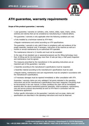
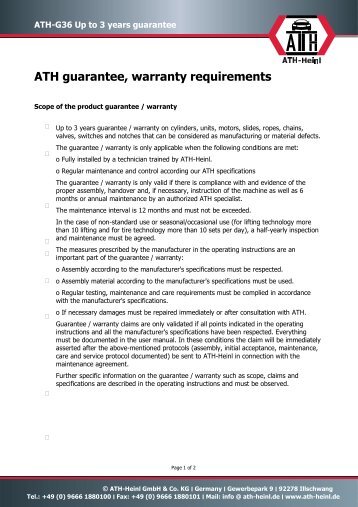
7.1 Alcance de la garantía del pro
- Seite 272 und 273:
8.1 Protocolo de instalación y tra
- Seite 274 und 275:
8.3 Inspección visual (especialist
- Seite 276 und 277:
Inspección visual (especialista au
- Seite 278 und 279:
9.0 NOTAS ® Copyright ATH-Heinl Gm
- Seite 280 und 281:
® Copyright ATH-Heinl GmbH & CO.KG
- Seite 282 und 283:
Bedieningshandleiding ATH-Comfort L
- Seite 284 und 285:
1.0 INLEIDING 1.1 Algemene informat
- Seite 286 und 287:
Hoofdonderdelen 1. Hefkolommen De i
- Seite 288 und 289:
1.3 Bediening Hoofdkolom 1. Knop He
- Seite 290 und 291:
1. Voorbereiding a. Lees voor gebru
- Seite 292 und 293:
1.4 Technische gegevens Draagvermog
- Seite 294 und 295:
1.5 Maatschets 2.50a 2.50s De aange
- Seite 296 und 297:
2.3 Leveringsomvang 1 Basispakket m
- Seite 298 und 299:
2.4 Opstellocatie De machine mag ni
- Seite 300 und 301:
2.7 Pneumatische aansluiting Bij al
- Seite 302 und 303:
® copyright ATH-Heinl GmbH & Co. K
- Seite 304 und 305:
Monteren Deze handleiding is niet b
- Seite 306 und 307:
3. Installeren en instellen van de
- Seite 308 und 309:
6. Monteer de synchronisatiekabels
- Seite 310 und 311:
9. Hydraulische olie a. Vul de hydr
- Seite 312 und 313:
3.2 Fundamentele aanwijzingen De ma
- Seite 314 und 315:
Minimale eisen voor vrachtwagenband
- Seite 316 und 317:
4.5 Storingen opsporen/storingsmeld
- Seite 318 und 319:
4.6 Onderhouds- en servicehandleidi
- Seite 320 und 321:
5.0 EG-/EU-KONFORMITÄTSERKLÄRUNG
- Seite 322 und 323:
6.2 Elektrisch schakelschema ® cop
- Seite 324 und 325:
6.3 Hydraulisch schakelschema Comfo
- Seite 326 und 327:
7.1 Omvang van de productgarantie
- Seite 328 und 329:
8.1 Opstellings- en overdrachtsrapp
- Seite 330 und 331:
8.3 Visuele inspectie (door geautor
- Seite 332 und 333:
Visuele inspectie (door geautorisee
- Seite 334 und 335:
9.0 NOTITIES ® copyright ATH-Heinl
- Seite 336 und 337:
® copyright ATH-Heinl GmbH & Co. K
- Seite 338 und 339:
Instrukcja Oblsugi ATH-Comfort Lift
- Seite 340 und 341:
1.0 WPROWADZENIE 1.1 Informacje og
- Seite 342 und 343:
Elementy główne 1. Kolumny podnos
- Seite 344 und 345:
1.3 Obsługa Kolumna główna 1. Pr
- Seite 346 und 347:
1. Przygotowanie a. Przed rozpoczę
- Seite 348 und 349:
1.4 Dane techniczne Nośność Wers
- Seite 350 und 351:
1.5 Zwymiarowany rysunek 2.50a 2.50
- Seite 352 und 353:
2.3 Zakres dostawy 1 Pakiet podstaw
- Seite 354 und 355:
2.4 Lokalizacja Maszynę należy tr
- Seite 356 und 357:
2.7 Przyłącze pneumatyczne W przy
- Seite 358 und 359:
® Prawa autorskie ATH-Heinl GmbH &
- Seite 360 und 361:
Montaż Niniejszej instrukcji nie n
- Seite 362 und 363:
3. Instalowanie i ustawianie zapade
- Seite 364 und 365:
6. Założyć liny współbieżne a
- Seite 366 und 367:
9. Olej hydrauliczny a. Uzupełnić
- Seite 368 und 369:
3.2 Podstawowe informacje Maszynę
- Seite 370 und 371:
Minimalne wymaganie dotyczące masz
- Seite 372 und 373:
4.5 Wyszukiwanie błędów / Sygnal
- Seite 374 und 375:
4.6 Instrukcje dotyczące konserwac
- Seite 376 und 377:
5.0 EG-/EU-KONFORMITÄTSERKLÄRUNG
- Seite 378 und 379:
6.2 Schemat obwodu elektrycznego ®
- Seite 380 und 381:
6.3 Schemat obwodu hydraulicznego C
- Seite 382 und 383:
7.1 Zakres gwarancji produktu • P
- Seite 384 und 385:
8.1 Protokół ustawiania i przekaz
- Seite 386 und 387:
8.3 Kontrola wzrokowa (upoważniona
- Seite 388 und 389:
Kontrola wzrokowa (upoważniona oso
- Seite 390 und 391:
9.0 NOTATKI ® Prawa autorskie ATH-
- Seite 392 und 393:
® Prawa autorskie ATH-Heinl GmbH &
- Seite 394 und 395:
Návod na Obsluhu ATH-Comfort Lift
- Seite 396 und 397:
1.0 ÚVOD 1.1 Všeobecné informác
- Seite 398 und 399:
Hlavné komponenty 1. Zdvižné st
- Seite 400 und 401:
1.3 Obsluha Hlavný stĺpik 1. Tla
- Seite 402 und 403:
Výrobok je určený na dvíhanie v
- Seite 404 und 405:
1.4 Technické údaje Nosnosť Verz
- Seite 406 und 407:
1.5 Rozmerový výkres 2.50a 2.50s
- Seite 408 und 409:
2.3 Rozsah dodávky 1 Základný ba
- Seite 410 und 411:
2.4 Umiestnenie Stroj by ste mali p
- Seite 412 und 413:
2.7 Pneumatické pripojenie Na vše
- Seite 414 und 415:
® Copyright ATH-Heinl GmbH & CO.KG
- Seite 416 und 417:
Montáž Tento návod neslúži ako
- Seite 418 und 419:
3. Inštalácia a nastavenie bezpe
- Seite 420 und 421:
6. Umiestnite súbehové laná a. L
- Seite 422 und 423:
9. Hydraulický olej a. Hydraulick
- Seite 424 und 425:
3.2 Zásadné upozornenia Stroj sm
- Seite 426 und 427:
Zariadenie stlačeného vzduchu Min
- Seite 428 und 429:
4.5 Hľadanie chýb/indikácia chyb
- Seite 430 und 431:
4.6 Návody na údržbu a servisné
- Seite 432 und 433:
5.0 EG-/EU-KONFORMITÄTSERKLÄRUNG
- Seite 434 und 435:
6.2 Schéma elektrického zapojenia
- Seite 436 und 437:
6.3 Schéma hydraulického zapojeni
- Seite 438 und 439:
7.1 Rozsah záruky na výrobok •
- Seite 440 und 441:
8.1 Protokol o umiestnení a odovzd
- Seite 442 und 443:
8.3 Zraková kontrola (povolanou od
- Seite 444 und 445:
Zraková kontrola (povolanou odborn
- Seite 446 und 447:
9.0 POZNÁMKY ® Copyright ATH-Hein
- Seite 448 und 449:
® Copyright ATH-Heinl GmbH & CO.KG


LinkedIn
Facebook
Instagram
Youtube
Email
Twitter
Pinterest