- Seite 1 und 2:
Deutsch English Polskie Français
- Seite 3 und 4:
Inhalt 1.0 EINLEITUNG .............
- Seite 5 und 6:
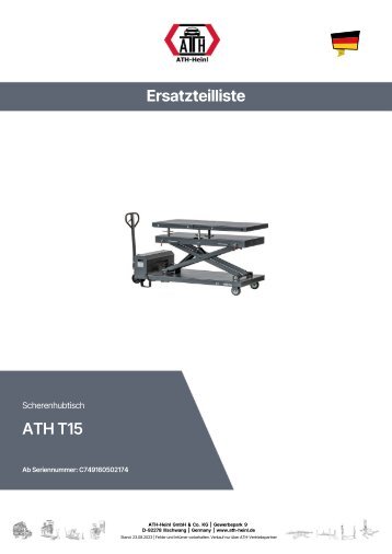
1.2 Beschreibung Abdeckung oben Um
- Seite 7 und 8:
1.3 Bedienung Taster Heben um Hebeb
- Seite 9 und 10:
Sicherheitshinweise 1. Achten Sie a
- Seite 11 und 12:
Traglastverteilung Q Gesamtgewicht
- Seite 13 und 14:
® Urheberrecht ATH-Heinl GmbH & CO
- Seite 15 und 16:
2.3 Lieferumfang Transportbox mit:
- Seite 17 und 18:
2.5 Befestigung Hierbei sind die al
- Seite 19 und 20:
2.9 Montage Diese Anleitung ist nic
- Seite 21 und 22:
Installation des Netzteils Setzen S
- Seite 23 und 24:
Anschluss der Hydraulikleitung Acht
- Seite 25 und 26:
2.10 Abschlussarbeiten Prüfen Sie
- Seite 27 und 28:
Kontrolle des Endschalters für ein
- Seite 29 und 30:
3.0 BETRIEB 3.1 Betriebsanweisung F
- Seite 31 und 32:
4.0 WARTUNG Um einen sicheren Betri
- Seite 33 und 34:
4.3 Hinweise Die Maschine ist, unab
- Seite 35 und 36:
Probleme beim Senken Sicherheitsras
- Seite 37 und 38: 4.7 Entsorgung • Entfernen Sie di
- Seite 39 und 40: 6.0 ANHANG 6.1 Pneumatik-Schaltplan
- Seite 41 und 42: 6.3 Hydraulik-Schaltplan 1 Ölfilte
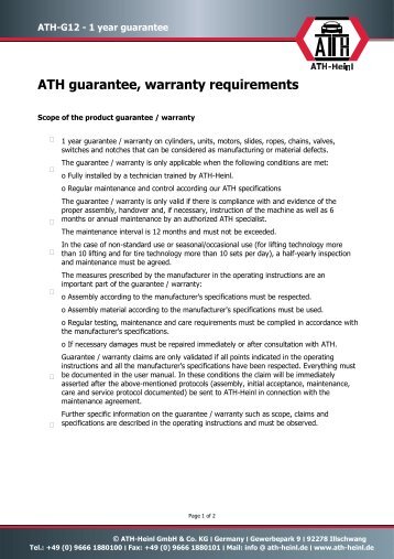
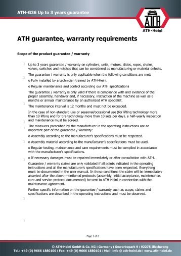
- Seite 43 und 44: 7.1 Umfang der Produktgarantie •
- Seite 45 und 46: 8.1 Aufstellungs- und Übergabeprot
- Seite 47 und 48: 8.3 Sichtprüfung (Befugte Sachkund
- Seite 49 und 50: Sichtprüfung (Befugte Sachkundige
- Seite 51 und 52: 9.0 NOTIZEN ® Urheberrecht ATH-Hei
- Seite 53 und 54: www.ath-heinl.de ATH-Heinl GmbH & C
- Seite 55 und 56: Contents 1.0 INTRODUCTION .........
- Seite 57 und 58: 1.2 Description Hat To cover the co
- Seite 59 und 60: 1.3 Operation Push button lifting (
- Seite 61 und 62: Safety instructions 1. Check the co
- Seite 63 und 64: Load distribution Q Total weight of
- Seite 65 und 66: ® Copyright ATH-Heinl GmbH & Co. K
- Seite 67 und 68: 2.3 Delivery Contents Transport box
- Seite 69 und 70: 2.5 Fixing General and local regula
- Seite 71 und 72: 2.9 Assembly These instructions are
- Seite 73 und 74: Installation Of Power Unit Place th
- Seite 75 und 76: Hydraulic line connection Take care
- Seite 77 und 78: 2.10 Completion of Work Before comm
- Seite 79 und 80: Installation of front cover Front c
- Seite 81 und 82: 3.0 OPERATION 3.1 Operating Instruc
- Seite 83 und 84: 4.0 MAINTENANCE The user must maint
- Seite 85 und 86: 4.3 Notes Regardless of the level o
- Seite 87: Lowering Problems Check cable conne
- Seite 91 und 92: 6.0 APPENDIX 6.1 Pneumatic circuit
- Seite 93 und 94: 6.3 Hydraulic circuit diagram 1 Oil
- Seite 95 und 96: 7.1 Scope of the Product Warranty
- Seite 97 und 98: 8.1 Installation and Handover Log S
- Seite 99 und 100: 8.3 Visual inspection (authorised e
- Seite 101 und 102: Visual inspection (authorised exper
- Seite 103 und 104: 9.0 NOTES ® Copyright ATH-Heinl Gm
- Seite 105 und 106: www.ath-heinl.de ATH-Heinl GmbH & C
- Seite 107 und 108: Sommaire 1.0 INTRODUCTION .........
- Seite 109 und 110: 1.2 Description Couvrir sur le dess
- Seite 111 und 112: 1.3 Utilisation Bouton d'ascenseur
- Seite 113 und 114: consignes de sécurité 1. Faites a
- Seite 115 und 116: Répartition de la charge Q Poids t
- Seite 117 und 118: ® Droit d'auteur ATH-Heinl GmbH &
- Seite 119 und 120: 2.3 Livraison Caisse de transport a
- Seite 121 und 122: 2.5 Fixation Il convient ici de res
- Seite 123 und 124: 2.9 Montage Ce manuel ne doit pas
- Seite 125 und 126: Installation de l'alimentation Plac
- Seite 127 und 128: Raccordement de la ligne hydrauliqu
- Seite 129 und 130: 2.10 Travaux finaux Avant la mise e
- Seite 131 und 132: Vérifier le bon fonctionnement de
- Seite 133 und 134: 3.0 EXPLOITATION 3.1 Manuel d'utili
- Seite 135 und 136: 4.0 MAINTENANCE Afin de garantir le
- Seite 137 und 138: 4.3 Remarques Quel que soit l'état
- Seite 139 und 140:
Problèmes lors de l'abaissement Le
- Seite 141 und 142:
4.7 Élimination • Coupez l'alime
- Seite 143 und 144:
6.0 ANNEXE 6.1 Schéma pneumatique
- Seite 145 und 146:
6.3 Schéma hydraulique 1 Filtre à
- Seite 147 und 148:
7.1 Étendue de la garantie produit
- Seite 149 und 150:
8.1 Procès-verbal d'installation e
- Seite 151 und 152:
8.3 Contrôle visuel (personne qual
- Seite 153 und 154:
Contrôle visuel (personne qualifi
- Seite 155 und 156:
9.0 NOTICES ® Droit d'auteur ATH-H
- Seite 157 und 158:
www.ath-heinl.de ATH-Heinl GmbH & C
- Seite 159 und 160:
Spis treści 1.0 WPROWADZENIE .....
- Seite 161 und 162:
1.2 Opis Pokrywa na górze Aby zakr
- Seite 163 und 164:
1.3 Obsługa Przycisk podnoszenia p
- Seite 165 und 166:
Instrukcje bezpieczeństwa 1. Zwró
- Seite 167 und 168:
Rozkład obciążenia Q Całkowita
- Seite 169 und 170:
® Prawa autorskie ATH-Heinl GmbH &
- Seite 171 und 172:
2.3 Zakres dostawy Skrzynia transpo
- Seite 173 und 174:
2.5 Mocowanie W tym przypadku nale
- Seite 175 und 176:
2.9 Montaż Niniejszej instrukcji n
- Seite 177 und 178:
Instalacja zasilacza Umieść zasil
- Seite 179 und 180:
Podłączenie linii hydraulicznej U
- Seite 181 und 182:
2.10 Prace końcowe Przed uruchomie
- Seite 183 und 184:
Sprawdź, czy wyłącznik krańcowy
- Seite 185 und 186:
3.0 PRACA 3.1 Instrukcja eksploatac
- Seite 187 und 188:
4.0 KONSERWACJA Aby zapewnić bezpi
- Seite 189 und 190:
4.3 Wskazówki Bez względu na zani
- Seite 191 und 192:
Problemy z opuszczaniem Winda sama
- Seite 193 und 194:
4.7 Utylizacja • Odłączyć dop
- Seite 195 und 196:
6.0 ZAŁĄCZNIK 6.1 Schemat obwodu
- Seite 197 und 198:
6.3 Schemat obwodu hydraulicznego 1
- Seite 199 und 200:
7.1 Zakres gwarancji produktu • P
- Seite 201 und 202:
8.1 Protokół ustawiania i przekaz
- Seite 203 und 204:
8.3 Kontrola wzrokowa (upoważniona
- Seite 205 und 206:
Kontrola wzrokowa (upoważniona oso
- Seite 207 und 208:
9.0 NOTIZEN ® Prawa autorskie ATH-
- Seite 209:
www.ath-heinl.de ATH-Heinl GmbH & C


LinkedIn
Facebook
Instagram
Youtube
Email
Twitter
Pinterest