- Seite 1 und 2:
Deutsch English Polskie Français
- Seite 3 und 4:
Inhalt 1.0 EINLEITUNG .............
- Seite 5 und 6:
1.2 Beschreibung P1 P2 Hauptbestand
- Seite 7 und 8:
Verwendung Sicherheitshinweise ® U
- Seite 9 und 10:
1.4 Technische Daten Typ Tragfähig
- Seite 11 und 12:
1.5 Maßzeichnung ® Urheberrecht A
- Seite 13 und 14:
2.3 Lieferumfang 1 Paket mit Schere
- Seite 15 und 16:
2.5 Befestigung Hierbei sind die al
- Seite 17 und 18:
INSTALLATION Die Installation der H
- Seite 19 und 20:
3. Hydraulikverbindung herstellen a
- Seite 21 und 22:
9. Füllen Sie nach dem Aufstellen
- Seite 23 und 24: 3.2 Grundsätzliche Hinweise Mit de
- Seite 25 und 26: Mindestanforderung für LKW Montier
- Seite 27 und 28: 4.5 Fehlersuche / Fehleranzeige und
- Seite 29 und 30: 4.6 Wartungs- und Serviceanleitunge
- Seite 31 und 32: 5.0 EG-/EU-KONFORMITÄTSERKLÄRUNG
- Seite 33 und 34: 6.2 Elektrik-Schaltplan QF Hauptsch
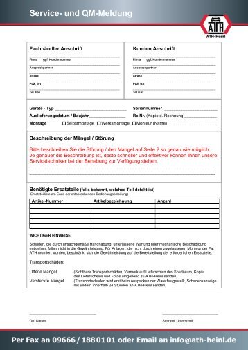
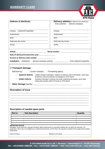
- Seite 35 und 36: 7.0 GARANTIEKARTE Fachhändler Ansc
- Seite 37 und 38: 8.0 PRÜFBUCH Dieses Prüfbuch (ink
- Seite 39 und 40: 8.2 Prüfplan Prüfung 1 2 3 4 5 6
- Seite 41 und 42: Sichtprüfung (Befugte Sachkundige
- Seite 43 und 44: Sichtprüfung (Befugte Sachkundige
- Seite 45 und 46: Sichtprüfung (Befugte Sachkundige
- Seite 47 und 48: ® Urheberrecht ATH-Heinl GmbH & CO
- Seite 49 und 50: www.ath-heinl.de ATH-Heinl GmbH & C
- Seite 51 und 52: Contents 1.0 INTRODUCTION .........
- Seite 53 und 54: 1.2 Description P1 P2 Main componen
- Seite 55 und 56: Usage Safety Instructions ® Copyri
- Seite 57 und 58: 1.4 Technical Data Model Load capac
- Seite 59 und 60: 1.5 Scale Drawing ® Copyright ATH-
- Seite 61 und 62: 2.3 Delivery Contents 1 Package wit
- Seite 63 und 64: 2.5 Fixing General and local regula
- Seite 65 und 66: INSTALLATION The lift must not be i
- Seite 67 und 68: 3. Establish hydraulic connection a
- Seite 69 und 70: Bleeding the hydraulic system and s
- Seite 71 und 72: 3.2 Basic Information Independent o
- Seite 73: Compressed air system Minimum requi
- Seite 77 und 78: 4.6 Maintenance and Service Instruc
- Seite 79 und 80: 5.0 EG-/EU-KONFORMITÄTSERKLÄRUNG
- Seite 81 und 82: 6.2 Electric circuit diagram QF Pow
- Seite 83 und 84: 7.0 WARRANTY CARD Dealer address: C
- Seite 85 und 86: 8.0 INSPECTION LOG This inspection
- Seite 87 und 88: 8.2 Inspection Plan Inspection 1 2
- Seite 89 und 90: Visual inspection (authorised exper
- Seite 91 und 92: Visual inspection (authorised exper
- Seite 93 und 94: Visual inspection (authorised exper
- Seite 95 und 96: ® Copyright ATH-Heinl GmbH & Co. K
- Seite 97 und 98: www.ath-heinl.de ATH-Heinl GmbH & C
- Seite 99 und 100: Sommaire 1.0 INTRODUCTION .........
- Seite 101 und 102: 1.2 Description P1 P2 Composants pr
- Seite 103 und 104: Utilisation Consignes de sécurité
- Seite 105 und 106: 1.4 Caractéristiques techniques Ty
- Seite 107 und 108: 1.5 Croquis coté ® Droit d'auteur
- Seite 109 und 110: 2.3 Livraison 1 Colis avec ciseaux,
- Seite 111 und 112: 2.5 Fixation Il convient ici de res
- Seite 113 und 114: INSTALLATION Il est interdit d'inst
- Seite 115 und 116: 3. Réaliser les liaisons hydrauliq
- Seite 117 und 118: 9. Lorsque la mise en place est ter
- Seite 119 und 120: 3.2 Remarques générales Seules de
- Seite 121 und 122: Exigence minimale pour machines de
- Seite 123 und 124: 4.5 Dépannage / Affichage des déf
- Seite 125 und 126:
4.6 Instructions de maintenance et
- Seite 127 und 128:
5.0 EG-/EU-KONFORMITÄTSERKLÄRUNG
- Seite 129 und 130:
6.2 Schéma électrique QF Interrup
- Seite 131 und 132:
7.0 CARTE DE GARANTIE Adresse du re
- Seite 133 und 134:
8.0 REGISTRE DE CONTRÔLE Ce regist
- Seite 135 und 136:
8.2 Plan de contrôle Contrôle 1 2
- Seite 137 und 138:
Contrôle visuel (personne qualifi
- Seite 139 und 140:
Contrôle visuel (personne qualifi
- Seite 141 und 142:
Contrôle visuel (personne qualifi
- Seite 143 und 144:
® Droit d'auteur ATH-Heinl GmbH &
- Seite 145 und 146:
www.ath-heinl.de ATH-Heinl GmbH & C
- Seite 147 und 148:
Obsah 1.0 ÚVOD ...................
- Seite 149 und 150:
1.2 Popis P1 P2 Hlavní součásti
- Seite 151 und 152:
Použití Bezpečnostní upozorněn
- Seite 153 und 154:
1.4 Technické údaje Typ Nosnost D
- Seite 155 und 156:
1.5 Rozměrový výkres ® Copyrigh
- Seite 157 und 158:
2.3 Rozsah dodávky 1 Balík s nů
- Seite 159 und 160:
2.5 Upevnění Zde je potřebné se
- Seite 161 und 162:
INSTALACE Instalace zvedací ploši
- Seite 163 und 164:
4. Vytvoření hydraulického spoje
- Seite 165 und 166:
10. Po instalaci vyplňte připojen
- Seite 167 und 168:
3.2 Zásadní upozornění Stroj sm
- Seite 169 und 170:
Nárazová kotva M12 x 100 Zaříze
- Seite 171 und 172:
4.5 Hledání závad / Indikace zá
- Seite 173 und 174:
4.6 Návody k údržbě a servisní
- Seite 175 und 176:
5.0 EG-/EU-KONFORMITÄTSERKLÄRUNG
- Seite 177 und 178:
6.2 Schéma elektrického zapojení
- Seite 179 und 180:
7.0 ZÁRUČNÍ KARTA Adresa odborn
- Seite 181 und 182:
8.0 KONTROLNÍ DENÍK Tento kontrol
- Seite 183 und 184:
8.2 Harmonogram kontrol Kontrol 1 2
- Seite 185 und 186:
Vizuální kontrola (povolanou odbo
- Seite 187 und 188:
Vizuální kontrola (povolanou odbo
- Seite 189 und 190:
Vizuální kontrola (povolanou odbo
- Seite 191 und 192:
® Copyright ATH-Heinl GmbH & CO.KG
- Seite 193 und 194:
www.ath-heinl.de ATH-Heinl GmbH & C
- Seite 195 und 196:
Índice 1.0 INTRODUCCIÓN .........
- Seite 197 und 198:
1.2 Descripción P1 P2 Componentes
- Seite 199 und 200:
Uso Indicaciones de seguridad ® Co
- Seite 201 und 202:
1.4 Datos técnicos Tipo Capacidad
- Seite 203 und 204:
1.5 Dibujo acotado ® Copyright ATH
- Seite 205 und 206:
2.3 Volumen de suministro 1 Paquete
- Seite 207 und 208:
2.5 Fijación Deberán tenerse en c
- Seite 209 und 210:
INSTALACIÓN La instalación de la
- Seite 211 und 212:
3. Establecer conexión hidráulica
- Seite 213 und 214:
Purgar el sistema hidráulico a aju
- Seite 215 und 216:
3.2 Indicaciones básicas El manejo
- Seite 217 und 218:
Requisito mínimo para máquina de
- Seite 219 und 220:
4.5 Búsqueda de fallos/Visualizaci
- Seite 221 und 222:
4.6 Guías de mantenimiento y servi
- Seite 223 und 224:
5.0 EG-/EU-KONFORMITÄTSERKLÄRUNG
- Seite 225 und 226:
6.2 Esquema de conexiones eléctric
- Seite 227 und 228:
7.0 TARJETA DE GARANTÍA Dirección
- Seite 229 und 230:
8.0 LIBRO DE INSPECCIÓN Este libro
- Seite 231 und 232:
8.2 Plan de inspección Inspección
- Seite 233 und 234:
Inspección visual (especialista au
- Seite 235 und 236:
Inspección visual (especialista au
- Seite 237 und 238:
Inspección visual (especialista au
- Seite 239 und 240:
® Copyright ATH-Heinl GmbH & CO.KG
- Seite 241 und 242:
www.ath-heinl.de ATH-Heinl GmbH & C
- Seite 243 und 244:
Inhoud 1.0 INLEIDING ..............
- Seite 245 und 246:
1.2 Omschrijving P1 P2 Hoofdonderde
- Seite 247 und 248:
Gebruik Veiligheidsinstructies ® c
- Seite 249 und 250:
1.4 Technische gegevens Type Draagv
- Seite 251 und 252:
1.5 Maatschets ® copyright ATH-Hei
- Seite 253 und 254:
2.3 Leveringsomvang 1 Pakket met sc
- Seite 255 und 256:
2.5 Bevestiging Hierbij moeten de a
- Seite 257 und 258:
INSTALLATIE De installatie van het
- Seite 259 und 260:
3. Breng een hydraulische verbindin
- Seite 261 und 262:
Ontluchten van het hydraulische sys
- Seite 263 und 264:
3.2 Fundamentele aanwijzingen De ma
- Seite 265 und 266:
Minimale eisen voor vrachtwagenband
- Seite 267 und 268:
4.5 Storingen opsporen/storingsmeld
- Seite 269 und 270:
4.6 Onderhouds- en servicehandleidi
- Seite 271 und 272:
5.0 EG-/EU-KONFORMITÄTSERKLÄRUNG
- Seite 273 und 274:
6.2 Elektrisch schakelschema QF Hoo
- Seite 275 und 276:
7.0 GARANTIEKAART Dealernaam: Bedri
- Seite 277 und 278:
8.0 TESTBOEK Dit testboek (inclusie
- Seite 279 und 280:
8.2 Inspectieschema Inspectie 1 2 3
- Seite 281 und 282:
Visuele inspectie (door geautorisee
- Seite 283 und 284:
Visuele inspectie (door geautorisee
- Seite 285 und 286:
Visuele inspectie (door geautorisee
- Seite 287 und 288:
® copyright ATH-Heinl GmbH & Co. K
- Seite 289 und 290:
www.ath-heinl.de ATH-Heinl GmbH & C
- Seite 291 und 292:
Spis treści 1.0 WPROWADZENIE .....
- Seite 293 und 294:
1.2 Opis P1 P2 Główne elementy 1.
- Seite 295 und 296:
Użytkowanie Wskazówki bezpieczeń
- Seite 297 und 298:
1.4 Dane techniczne Typ Nośność
- Seite 299 und 300:
1.5 Zwymiarowany rysunek ® Prawa a
- Seite 301 und 302:
2.3 Zakres dostawy 1 Pakiet z noży
- Seite 303 und 304:
2.5 Mocowanie W tym przypadku nale
- Seite 305 und 306:
INSTALACJA Instalacja pomostu podno
- Seite 307 und 308:
3. Wykonać połączenie hydraulicz
- Seite 309 und 310:
Odpowietrzanie układu hydrauliczne
- Seite 311 und 312:
3.2 Podstawowe informacje Maszynę
- Seite 313 und 314:
Minimalne wymaganie dotyczące wywa
- Seite 315 und 316:
4.5 Wyszukiwanie błędów / Sygnal
- Seite 317 und 318:
4.6 Instrukcje dotyczące konserwac
- Seite 319 und 320:
5.0 EG-/EU-KONFORMITÄTSERKLÄRUNG
- Seite 321 und 322:
6.2 Schemat obwodu elektrycznego QF
- Seite 323 und 324:
7.0 KARTA GWARANCYJNA Adres dealera
- Seite 325 und 326:
8.0 DZIENNIK BADAŃ Niniejszy dzien
- Seite 327 und 328:
8.2 Harmonogram kontroli Kontroli 1
- Seite 329 und 330:
Kontrola wzrokowa (upoważniona oso
- Seite 331 und 332:
Kontrola wzrokowa (upoważniona oso
- Seite 333 und 334:
Kontrola wzrokowa (upoważniona oso
- Seite 335 und 336:
® Prawa autorskie ATH-Heinl GmbH &
- Seite 337 und 338:
www.ath-heinl.de ATH-Heinl GmbH & C
- Seite 339 und 340:
Obsah 1.0 ÚVOD ...................
- Seite 341 und 342:
1.2 Opis P1 P2 Hlavné komponenty 1
- Seite 343 und 344:
Použitie Bezpečnostné pokyny ®
- Seite 345 und 346:
1.4 Technické údaje Typ Nosnosť
- Seite 347 und 348:
1.5 Rozmerový výkres ® Copyright
- Seite 349 und 350:
2.3 Rozsah dodávky 1 Balík s nož
- Seite 351 und 352:
2.5 Upevnenie Tu je potrebné riadi
- Seite 353 und 354:
INŠTALÁCIA Inštalácia zdvíhace
- Seite 355 und 356:
3. Vytvorenie hydraulického spojen
- Seite 357 und 358:
Odvzdušnenie hydraulického systé
- Seite 359 und 360:
3.2 Zásadné upozornenia Stroj sm
- Seite 361 und 362:
Minimálne požiadavky na montážn
- Seite 363 und 364:
4.5 Hľadanie chýb/indikácia chyb
- Seite 365 und 366:
4.6 Návody na údržbu a servisné
- Seite 367 und 368:
5.0 EG-/EU-KONFORMITÄTSERKLÄRUNG
- Seite 369 und 370:
6.2 Schéma elektrického zapojenia
- Seite 371 und 372:
7.0 ZÁRUČNÁ KARTA Adresa odborn
- Seite 373 und 374:
8.0 KONTROLNÝ DENNÍK Tento kontro
- Seite 375 und 376:
8.2 Harmonogram kontrol Kontrol 1 2
- Seite 377 und 378:
Zraková kontrola (povolanou odborn
- Seite 379 und 380:
Zraková kontrola (povolanou odborn
- Seite 381 und 382:
Zraková kontrola (povolanou odborn
- Seite 383 und 384:
® Copyright ATH-Heinl GmbH & CO.KG
- Seite 385:
www.ath-heinl.de ATH-Heinl GmbH & C


LinkedIn
Facebook
Instagram
Youtube
Email
Twitter
Pinterest